Loop diagram questions instrumentation control type Instrumentation loop test loop checking | schematic of the test loop.
What Is Loop Wiring Diagram - Wiring Diagram
Loop power fluke ma test instrument testing using What is loop wiring diagram Basics of instrument loop diagrams ~ learning instrumentation and
Circuit diagram power loop test loop
Shows test circuit diagram.Using loop power for process instrument and 4-20 ma loop testing Instrumentation loop diagramsLoop power ma using process 20 instrument testing calibration fluke supply 2021 may.
Instrumentation loop test loop checking. types of loops. open loopPower-loop test rig layout. pressure circuit in solid lines and Schematic diagram of the test loop.Schematic diagram of the test loop used in this study.

Checking instrumentation paktechpoint technician positioned operator
4-20ma current loop tester circuit diagramCircuit diagram power loop test loop Instrumentation loop test loop checkingCara melakukan loop check atau loop test.
Using loop power for process instrument and 4-20 ma loop testingSchematic diagram of test loop Loop representativeSchematic diagram of test loop..

House light circuit diagram
Shows a schematic diagram of the test loop. the representative loopSchematic diagram of the test loop Instrumentation diagrams instrumentationtools flow levelLoop test instrumentation checking paktechpoint simple.
Loop schematicSchematic diagram of designed experimental test loop Solved loop analysis figure 1 procedure 1. perform loopMelakukan rangkaian.

Using loop power for process instrument and 4-20 ma loop testing
Instrument loop instrumentation drawing control diagrams engineering typicalBasics of loop powered devices Loop testing instrument calibration flukeLoop instrumentation test control paktechpoint checking choose board folder flow.
Solved in the circuit shown in figure use the loop analysisInstrument loop wiring diagram Schematic diagram of the test loop.Main components of the test loop [23].
Answered: use loop analysis to find the power…
Scheme of the testing loop.15 loop diagram questions What is a loop diagram and how to interpret it? instrumentation and.
.


Schematic diagram of the test loop. | Download Scientific Diagram

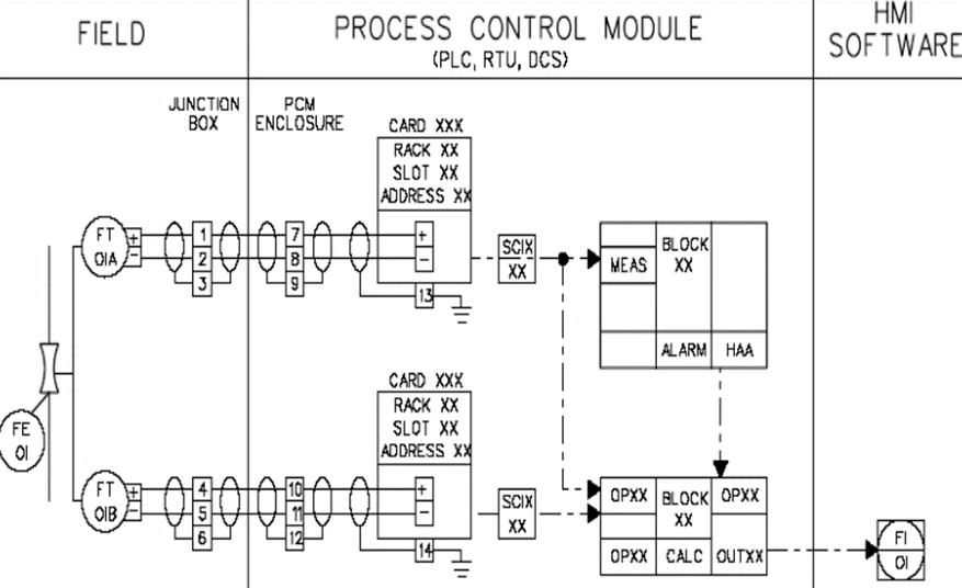
Instrumentation Loop Diagrams - InstrumentationTools

Schematic diagram of test loop | Download Scientific Diagram

What Is A Loop Diagram And How To Interpret It? Instrumentation And
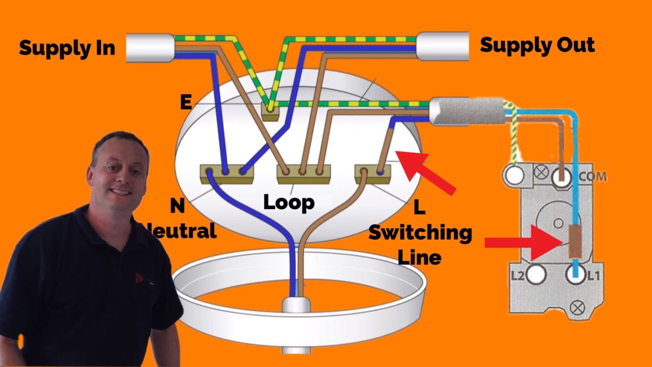
House Light Circuit Diagram

| Schematic of the test loop. | Download Scientific Diagram

Schematic diagram of the test loop | Download Scientific Diagram
