Locked configuration Ic 565 pll Circuit pll phase diagram multiplier lock loop frequency tc
Phase Locked Loop IC
Phase locked loops pll block diagram, operating principle, ic 565 Application of pll 565 as fsk demodulator Phase locked loop (pll) – mohan's electronics blog
Pll block locked principle loops
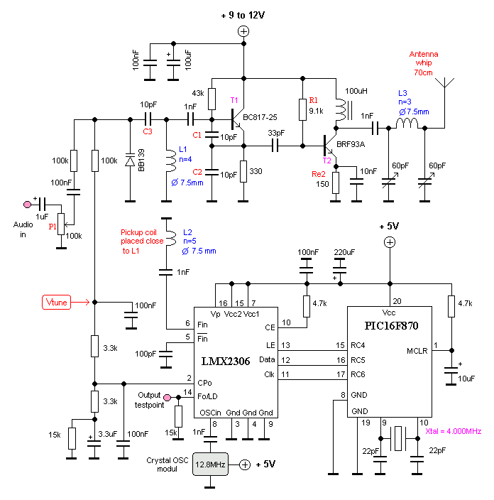
Fm demodulation using zero crossing detector : envelope detection usingPll ic 565 Mạch giải điều chế pll fmElectrical engineering: circuit diagram 500mw fm pll transmitter 88.
Pll applicationsLm565 ic : pin configuration, specifications, circuit & its applications Ic 565 pll circuits electronics phase integrated loop block dual tutorial schematic supply locked lm operatedPll fm using detector 565 ic circuit frequency circuits diagram voltage converter simple full deviation gr next above size click.

565 ic pll loop phase electronics tutorial locked features frequency
Monolithic pll ic 565 applicationsPhase locked loop ic Pll ic 565Pll circuit diagram.
Pll ic procedurePll-phase locked loops,block diagram,working,operation,design,applications Frequency multiplier circuitFrequency multiplier circuit using pll divider diagram programmable thumbwheel switches projects parts list.

Lm565 pll ic pinout, features & datasheet
Pll block diagram locked loop phase ic important featuresLm565 ic : pin configuration, specifications, circuit & its applications Pll ic 565Pll fm detector using pll ic 565 under repository-circuits -37941.
Ic 565 pll || phase locked loop || pin diagram || block diagramFrequency multiplier using pll-565 Diagram 565 pll ic ne block phase se locked loop circuits565 ic phase loop lock using pll frequency rt determined formula connected components ct external running.

Frequency multiplier using pll 565
Phase locked loop icDemodulation detector 565 pll farm6 detection Monolithic pll ic 565 applicationsFrequency multiplier using pll circuit diagram.
Schematic diagram of the pll simulation circuitLm565锁相环ic pinout, features & datasheet Ic 565 pllFrequency multiplier pll circuit.

Pll circuit diagram pdf
Phase lock loop using ic 565Pll applications frequency electronics tutorial resistor consists varied r1 vco pot c1 help Fsk frequency generator shift keying pll using circuit diagram receiver vco signal projects fmPhase lock loop (pll) lm565 circuit.
Frequency shift keying (fsk) generator using pll 565 .


Frequency Shift Keying (FSK) Generator Using PLL 565

electrical engineering: Circuit diagram 500mW FM PLL transmitter 88

PLL IC 565 | Analog-integrated-circuits || Electronics Tutorial

IC 565 - PLL Applications - IC Applications and HDL Simulation Lab

Frequency Multiplier using PLL 565 | Block and Connection Diagram
Application of PLL 565 as FSK Demodulator | Special Purpose Integrated

Phase Lock loop (PLL) LM565 Circuit